Flight Test
Modifications
Modifications
The rimfire 42x50x1000 is beyond repair. After some bad launches my conclusion is the fixed prop was bending the motor shaft and causing crunching noises. I have bought a new motor 42x50x800 rimfire as it has the same mounting bolt panel as the previous no longer available motor.
As it is only 800kv (800revs per volt) I am testing a steeper prop 10x12.
It is also a three blade folding prop (to hopefully resolve the issues of motor damage on bad launches / landings).


Static testing produced the following results:
rpm 8700
Volts 14.6
Amps 56
The motor and speed control started to get warm (hopefully not too much prop).
Flight test coming soon!


The Maiden
Thanks Jeff!

The rear hatch with the voltage telemetry meter and the electronic speed control for the motor.

The front hatch with batteries, Easy OSD and control wiring.


Camara and video transmission working.


A mixture of orange yellow and metallic brass paint.


Masking for lettering.


Getting some help with the painting.

Ready for detail painting.


Test fit for final installation of electronics.

Sprayed with final color coat. Metallic automotive finish.


Rear access door with steel glued at corners for magnetic latches.


Added in equipment bay door. The door is held shut with rare earth magnets.


Added wing tips with epoxy glue.


Added Velcro straps to hold in the battery and electronics. They are fiberglassed in to the base of the equipment bay.

First of final two prime coats. A very light sand in-between coats.


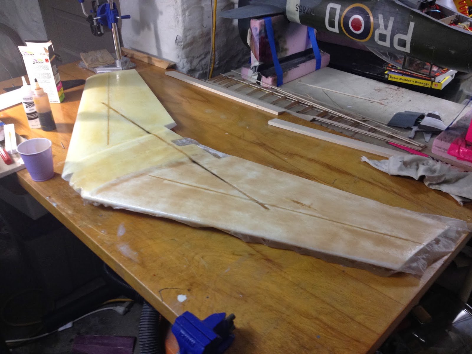
High build scratch filler primer was sprayed over the wing. 2 coats of a light gray and 2 coats of a dark gray. These were sanded using a block to reveal the high and low spots. A second application of scratch filler was used to fill and low points. High points were sanded down.


After the fiber glass had fully set up and was sanded, a thin coat of scratch filler was used to fill any of the weave that was still present.


Elevons are prepared, glassed and hinges installed. Hinges were glued using CA glue.


The antena was installed for future use. The antenna terminates in the receiver cut out in the wing.


Installing custom motor mount. I first cut of the short leg of the mount that came with the kit and made a new mounting plate with the screws lined up for the Rimfire motor. This was bolted in place, and the assembly was epoxied in place.
 |
| All electronics working. The GPS module started flashing once per second. The indicator that between 5 - 9 satelites are being detected. |


Receiver and battery connected to TV. GPS module
Everything plugged in and in approximately final location. Television image with OSD set to home.

Laying out the wiring and making a shielded video wire as it runs next to potentially noisy power.


Laser cut panels with cooling holes as the transmitter gets particularly hot.


Wood blocks added for countersunk screw taps to hold panels down.


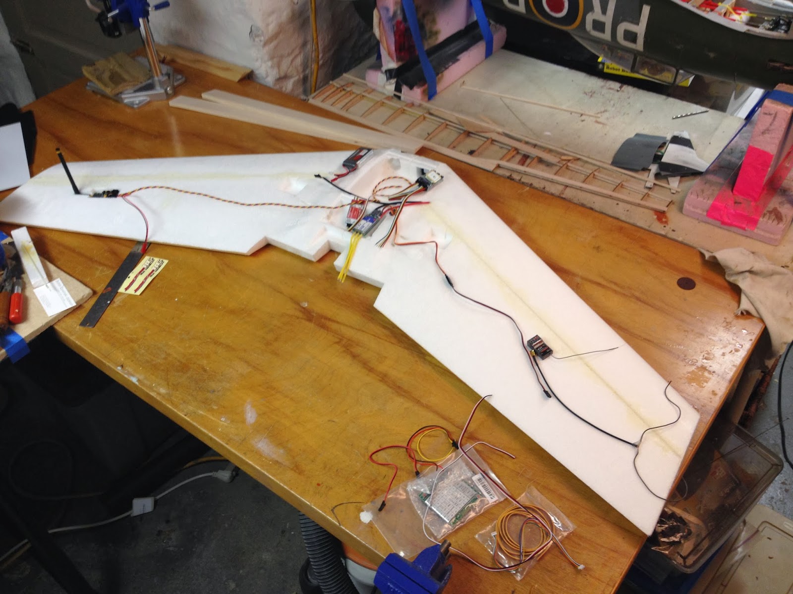
Now that the underside of the wing is glassed and better able to cope with hanger rash I set about wiring and creating all the necessary spaces for the electronics. This included creating all the wire runs, pulling the wire, and testing the electronics.

Both sides done. The epoxy resin will dry the same color.

One side done.

I fiber glassed the underside of the wing for protection. The top side of the wing will be left until the wiring and electronics is fully worked out and located.

Both cameras test fitted.

Shaping foam so there is no obstruction to camera line of site.

Replay XD test fitting. I will be adding protective fins to take any impact on a bad landing. Also the camera lens will be recessed behind the front of the foam.

Test fitting electronics and deciding the best layout. Once I get the motor and battery and OSD I will need to re-access for the COG.

Cut into the foam for the vtx. Going to develop this detail further to make a screw down vented cover for switching out antenna etc.

Gorilla glue shave down and ready for sanding.
Glued the two wing halves together with a two part epoxy and added the carbon fiber rods to stiffen the foam shell.

Gorilla glue foaming out of the rebar slots while curing.

Before joining the two wing halves I melted conduit tunnels into the center of the wings to run wiring for the various equipment.

Sorting the electrical equipment. Replay XD HD camera, 910mhz video transmitter, servos, speed control, video camera, control receiver.

Parts out of the box
I have purchased the Zephyr II kit from 'RightWing' and below is the construction and my set up in as I explore the world of FPV.
make sure to balance at the CG but also along the center line with the antenna on the outboard of the wing
ReplyDelete